

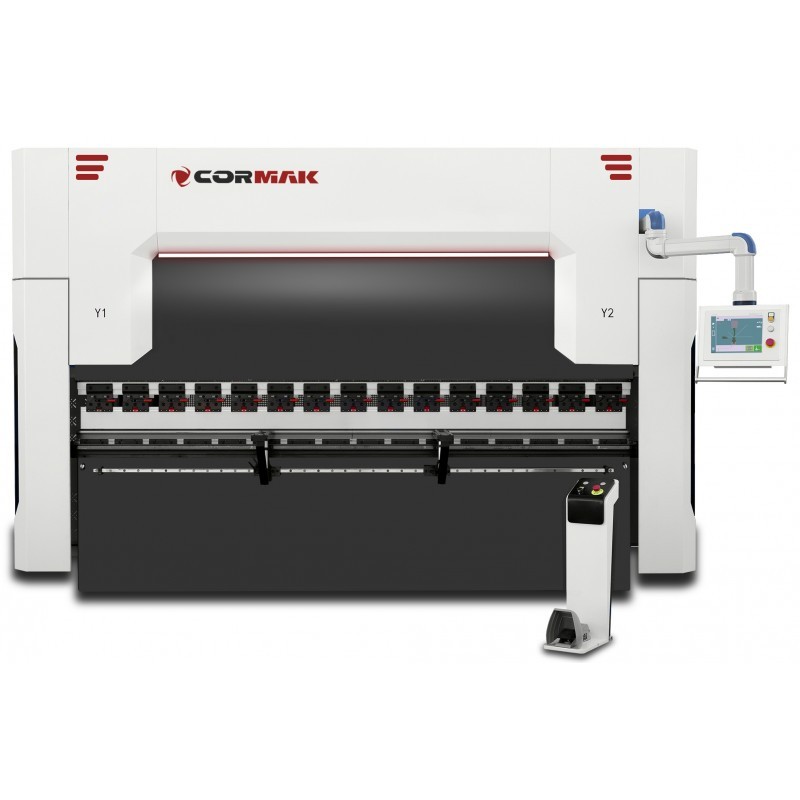
Choosing a CNC press brake involves more than comparing the number of controlled axes. Discover what Y1, Y2, X, R, Z1, Z2 and V do, how they affect bending accuracy and which configuration is most suitable for straightforward components, batch production and frequent changes between jobs.
When choosing a CNC press brake, it is easy to focus entirely on the number of controlled axes. Manufacturers offer three-, four-, six- and eight-axis machines, while more advanced configurations may provide additional controlled movements. However, more axes do not necessarily make a press brake a better investment. The right choice depends on component geometry, production volumes, changeover frequency and the required level of automation.
For many workshops, the basic Y1 + Y2 + X configuration is sufficient for straightforward bending. More complex components can benefit from the R axis and Z1/Z2 axes. For long bends, automatic deflection compensation, often identified as the V axis, is also important. Understanding these functions helps businesses invest in equipment suited to both current and future production requirements.
What do the axes on a CNC press brake mean?
Each axis controls a particular movement of the ram, backgauge or another machine mechanism. The CNC system positions these components according to the bending programme, reducing the need for repeated manual measurements and adjustments.
The most commonly encountered axes are:
- Y1 and Y2 – independent control of the left and right sides of the moving ram.
- X – positioning the backgauge at a specified distance from the bend line.
- R – vertical adjustment of the backgauge fingers.
- Z1 and Z2 – lateral movement of the backgauge fingers along the working width.
- X1 and X2 – independent depth positioning of two sections of the backgauge.
- V – control of the deflection compensation system, where fitted.
It is essential to distinguish automatically controlled CNC axes from manually adjusted mechanisms. Not every adjustable feature constitutes a separate CNC axis. The way manufacturers count axes can also differ between machines.
Y1 and Y2 – the foundation of accurate bending
On a hydraulic CNC press brake, Y1 and Y2 determine the positions of the left and right sides of the moving ram. Synchronised control maintains the required ram position relative to the bed and enables accurate setting of the lowest point of the bending stroke.
Positioning accuracy influences bend-angle repeatability. However, the finished result also depends on material properties, tooling, bending force and deflection compensation. An example of a machine with automatic ram positioning is the CORMAK CNC BASE 40×2000 press brake. The actual automation features should always be confirmed in the specification of the selected machine.
X axis – the most important backgauge axis
The X axis positions the backgauge at the programmed distance from the bend line. The operator places the sheet against the backgauge fingers and performs the bend without manually measuring each new position.
When a component requires several bends, the CNC automatically moves the backgauge between stages of the programme. This improves repeatability and reduces setting time. Consequently, Y1 + Y2 + X is a sensible starting point for most standard sheet-metal bending operations.
R axis – when is it genuinely useful?
The R axis controls the vertical position of the backgauge fingers. After the first bend, a component may have flanges or formed sections that prevent the next reference edge from resting correctly against fingers at a fixed height.
An automatically controlled R axis allows finger height to change at successive programme stages. This is especially useful for:
- profiles requiring multiple bends,
- tall flanges,
- box-shaped components,
- enclosures and metal cabinets,
- complex bending sequences.
Manual height adjustment can be adequate for simple work. For example, the CORMAK CNC SERVO EURO PB 125×2500 is described as having manual R adjustment, with a servo drive available as an option. Therefore, the presence of an R adjustment must not be confused with an automatically controlled CNC R axis.
Z1 and Z2 – important for frequently changing production
The Z1 and Z2 axes move the backgauge fingers left and right along the machine. On simpler press brakes, the operator adjusts the fingers manually. This may be entirely acceptable when producing the same component for several hours.
With frequent job changes, automatic Z axes enable the fingers to move to positions stored in the bending programme. This reduces changeover time and is particularly valuable for:
- small production batches,
- components of different widths,
- boxes, enclosures and cabinets,
- work involving numerous different programmes,
- orders requiring frequent machine adjustments.
Z axes do not carry out the bending operation directly. Instead, they improve flexibility when locating the workpiece. To assess the return on investment, consider how many finger-position changes are required during a typical production shift.
X1 and X2 – for more demanding components
A standard X axis positions the backgauge at a common depth. An X1/X2 arrangement allows two sections of the backgauge to be positioned independently. This can be useful for asymmetrical components, irregular shapes and reference edges that are not parallel to the bend line.
For ordinary profiles, enclosures and structural components, a single X axis will generally be sufficient. Before choosing X1/X2, check that the workpiece geometry genuinely requires independent reference depths and that the machine's backgauge design supports this type of positioning.
V axis – automatic deflection compensation
When bending under high loads, the bed and ram can undergo elastic deflection. Without suitable compensation, the bend angle in the centre of a long component may differ from the angles near its ends.
A crowning system, often designated the V axis, changes the geometry of the tooling support to compensate for this deflection. Depending on the machine configuration, the adjustment may be automatic. This is especially important for:
- long components,
- thicker sheet metal and high bending loads,
- tight bend-angle tolerances,
- batch production,
- large working lengths.
When considering a long press brake such as the CORMAK CNC SERVO EURO PB 250×6000, the crowning arrangement should be assessed carefully. Whether it is installed and automatically controlled must be confirmed for the individual machine configuration.
Is a press brake with the maximum number of axes worth buying?
Not always. A workshop producing mainly straightforward profiles and repeat components may use only a small proportion of the capabilities of an advanced multi-axis backgauge. Additional axes increase the purchase price and may also increase requirements for operation, calibration and servicing.
On the other hand, an overly basic configuration may restrict future production opportunities. Businesses should therefore assess both current work and planned developments. The real value of extra axes lies in the operations they make faster, more accurate or possible to manufacture.
Which axis configuration is best?
The following comparison provides a useful starting point. These configurations refer to automatically controlled CNC axes rather than manual adjustments.
| Configuration | Typical application | Main advantage |
|---|---|---|
| Y1 + Y2 + X | Simple bends and standard profiles | Basic automatic positioning |
| Y1 + Y2 + X + R | Multi-bend profiles and enclosures | Automatic finger-height adjustment |
| Y1 + Y2 + X + R + Z1 + Z2 | Flexible production and small batches | Faster backgauge changeovers |
| Additional V | Long bends and demanding tolerances | Reduced angle variation along the component |
A three-axis configuration may be adequate for straightforward workshop operations. Adding an automatic R axis is beneficial for more complicated shapes. Where jobs change frequently, Y1, Y2, X, R, Z1 and Z2 provide considerable flexibility. V-axis crowning should be selected according to bending length, loading and required accuracy.
When assessing medium-sized and larger machines, the capabilities of the CORMAK CNC SERVO EURO PB 200×3200 can be compared with actual production requirements. Optional features and the number of installed automatic axes should be confirmed in the specific quotation.
Axis count is not everything
Other important considerations include bending force, working length, daylight opening, ram stroke, positioning accuracy and speed, guide construction, frame rigidity, the hydraulic system and tooling quality.
A capable CNC controller should support convenient bending programme creation, storage of operating sequences and control of the installed axes. More advanced systems can provide graphical bending simulation, assistance with bend-sequence planning and identification of potential collisions.
One example of a press brake with a more advanced controller is the CORMAK CNC SERVO ELITE 200×3200 DA-58T. The controller's functions should not, however, be confused with the number of axes physically installed on the machine.
Before purchasing, it is advisable to review drawings of representative components and check the complete bending sequence. This also helps evaluate punch and die selection, flange heights and the risk of collisions with tooling or machine components.
Summary
The fundamental axes of a modern hydraulic CNC press brake are Y1, Y2 and X. They provide controlled ram movement and automatic backgauge positioning. An automatic R axis makes successive bends easier, while Z1 and Z2 improve efficiency when changing between different components.
For long workpieces, V-axis crowning helps achieve consistent bend angles along the working length. For many manufacturers, Y1 + Y2 + X + R + Z1 + Z2 offers a practical balance between investment cost and automation. The final decision should be based on component geometry, required tolerances and the manufacturer's confirmed equipment specification.
