


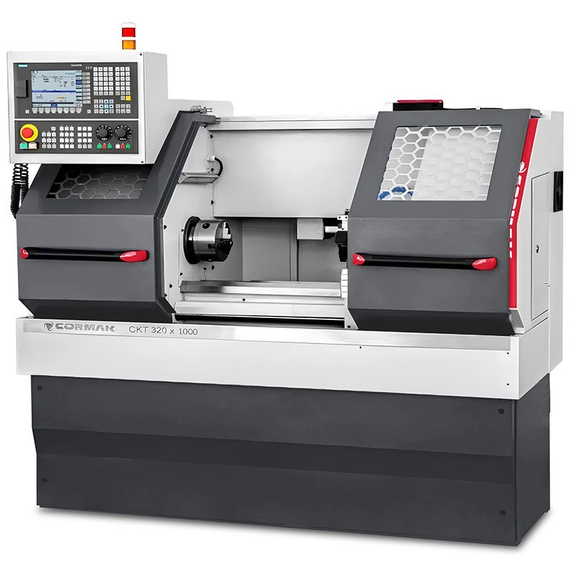
Smooth spindle speed control allows the operation of the CNC lathe to be adapted to the material, the workpiece diameter, the type of tool and the machining operation. It has a direct impact on surface quality, tool life, process stability and workplace safety.
Stepless spindle speed control allows the operation of a CNC lathe to be adapted to the material, workpiece diameter, tool type and machining operation. It has a direct impact on surface quality, tool life, process stability and workplace safety.
There is no single correct spindle speed for every situation. The parameters must be selected based on the cutting speed, the current diameter, the material grade, the geometry and grade of the insert, the feed rate, the cutting depth, the coolant, the machine power and the rigidity of the workpiece clamping.
What is stepless spindle speed control?
Stepless spindle speed control allows the rotational speed to be set within a wide range, rather than relying solely on a few fixed ratios. On a CNC lathe, the spindle speed can be set via the programme, the control panel or CAM software.
This function is particularly useful when a workshop machines different diameters and materials. It allows you to set the appropriate parameters for rough turning, finish turning, grooving, threading or face milling.
However, the rpm range alone does not determine the lathe’s capabilities. Other factors that matter include the available torque, spindle power, maximum speed, the rigidity of the machine–chuck–workpiece–tool system, and the limitations specified by the machine and chuck manufacturers.
Why is spindle speed important?
Spindle speed is determined by the cutting speed. If it is too high, it can accelerate tool wear, increase temperature and the risk of vibration. If it is too low, it can reduce productivity, impair chip formation or compromise surface quality. The correct setting should always be considered in conjunction with the feed rate and cutting depth.
Well-chosen parameters help to achieve:
- a more stable cutting process;
- more consistent surface quality;
- more predictable wear of the insert or cutter;
- better control over workpiece dimensions;
- a lower risk of vibration, build-up and tool damage.
The speed should be adjusted when the material, diameter, tool overhang, clamping method, cooling, type of machining or condition of the cutting edge changes. The data from the tool manufacturer’s catalogue is a starting point; the final parameters should be verified on the specific machine and for the specific operation.
How do you calculate spindle speed?
The following formula is used to determine an approximate rotational speed:
n = (1000 × Vc) / (π × D)
In workshop practice, the formula is often simplified as:
n = 318 × Vc / D
- n – spindle speed in rpm;
- Vc – cutting speed in m/min;
- D – current cutting diameter in mm;
- 318 – a rounded value of 1000/π.
Example for steel
Let us assume the turning of steel with a diameter of 50 mm at an approximate cutting speed of 120 m/min:
n = 318 × 120 / 50 = 763 rpm
In the programme, you can start with a value of around 760 rpm and then verify the result based on surface quality, chip formation, process noise, spindle load and the condition of the insert.
The formula does not take all machining conditions into account. The recommended cutting speed depends, amongst other things, on the material grade, hardness, cutting interruptions, cutting edge geometry, cooling and the required tool life.
Constant cutting speed in CNC: G96 and spindle speed limitation
In CNC turning, it is possible to work with either a constant spindle speed or a constant cutting speed. In many control systems, constant cutting speed mode is implemented using the G96 command, whilst constant spindle speed is implemented using the G97 command. The exact syntax depends on the control system, so you should always refer to the documentation for the specific machine.
With a constant cutting speed, the lathe automatically increases the spindle speed as the diameter decreases. This is advantageous for face turning and profiling, as it helps to maintain more consistent cutting conditions across a varying diameter.
It is essential to limit the maximum spindle speed. Near the workpiece’s axis, the diameter approaches zero and the calculated rpm increases very rapidly. In the programme, set the maximum spindle speed appropriate for the lathe, chuck, clamping and the workpiece’s balance. Do not exceed the limits specified by the machine tool or lathe chuck manufacturer.
A constant cutting speed is not always the best choice. For unbalanced workpieces, those with clamping limitations, certain threading operations, and where required by the manufacturing process or the manufacturer’s instructions, it may be safer to use constant speed control.
Cutting parameters for steel, aluminium and stainless steel
The values below are indicative for external turning under stable conditions. They do not replace the manufacturer’s data for a specific insert, HSS tool or recommendations for a particular material grade. For interrupted cutting, long overhangs, poor clamping or limited machine power, more conservative settings should be adopted.
Steel
Steel requires stable clamping, appropriate chipbreaker geometry and a suitable insert grade. For many common structural steels, indicative ranges may be as follows:
| Tool | Approximate cutting speed Vc | Notes |
|---|---|---|
| HSS cutter | 20–40 m/min | The value depends on the steel grade, cooling and cutting edge geometry. |
| Carbide insert | 80–180 m/min | Typical starting point for stable turning. |
| Coated insert for steel | 120–250 m/min | Selection depends on the ISO P grade, whether it is roughing or finishing, and the manufacturer’s specifications. |
In the event of excessive temperature, accelerated wear or vibration, check not only Vc but also the clamping, feed rate, cutting depth, overhang and cooling.
Aluminium
Aluminium is often machined at higher cutting speeds than steel. Sharp edges, positive geometry, effective chip evacuation and minimising build-up on the cutting edge are important.
| Tool | Approximate cutting speed Vc | Notes |
|---|---|---|
| HSS cutter | 60–120 m/min | Requires a sharp cutting edge and build-up control. |
| Carbide insert | 200–500 m/min | The range depends on the alloy, machine tool and cooling. |
| Polished insert for aluminium | 300–800 m/min | Higher Vc values are only possible under the conditions specified by the tool and machine manufacturers. |
For aluminium with a diameter of 40 mm and Vc = 300 m/min, the spindle speed is approximately 2385 rpm. Before applying this value, check the maximum rpm of the lathe, the chuck and the clamping method.
Stainless steel (INOX)
Stainless steels can be more demanding due to heat dissipation, work hardening and a tendency to build-up. They require stable clamping, the correct insert grade, the correct feed rate and adequate cooling.
| Tool | Approximate cutting speed Vc | Notes |
|---|---|---|
| HSS cutter | 10–25 m/min | Lower speeds, better control of temperature and cutting edge condition. |
| Carbide insert | 50–120 m/min | Selection depends on the grade of stainless steel and the stability of the setup. |
| Insert for stainless steel | 80–180 m/min | Follow the insert manufacturer’s specifications and cooling recommendations. |
When turning stainless steel, avoid ‘scraping’ the tool against the surface. The feed rate should ensure actual cutting, rather than the cutting edge merely sliding over the material, as this may promote surface hardening and accelerate tool wear.
Feed rate and cutting depth – parameters selected in conjunction with rotational speed
Cutting speed is just one of the parameters. In turning, the feed per revolution f, usually expressed in mm/rev, and the depth of cut ap, given in mm, are also important.
The feed rate can be calculated using the formula:
vf = n × f
- vf – feed rate in mm/min;
- n – spindle speed in rev/min;
- f – feed per revolution in mm/rev.
In finishing operations, lower feed rates are often used to minimise surface roughness. In roughing operations, the feed rate and depth of cut may be higher, provided that the machine’s power, workpiece stability, the cutting insert and chip removal conditions allow for this.
The feed rate should not be reduced indefinitely in an attempt to ‘improve the surface finish’. A feed rate that is too low in relation to the cutting edge geometry may lead to increased friction, poor chip formation and excessive heating. Parameters must be selected in accordance with the tool catalogue, the insert corner radius and the required surface quality.
Table of example spindle speeds
The table shows spindle speeds calculated using the formula n = 318 × Vc / D. These are guide values for the specified cutting speeds, not ready-made settings for every material and tool.
| Material | Cutting speed | Ø 20 mm | Ø 50 mm | Ø 100 mm |
|---|---|---|---|---|
| Steel | 120 m/min | 1908 rpm | 763 rpm | 382 rpm |
| Aluminium | 300 m/min | 4,770 rpm | 1,908 rpm | 954 rpm |
| Stainless steel | 80 m/min | 1,272 rpm | 509 rpm | 254 rpm |
At high speeds, the maximum permissible speed for the chuck, jaws, sleeves, clamping device and the workpiece itself is of particular importance. Before starting, ensure that the workpiece is correctly clamped and balanced within the limits of the particular workstation.
The most common mistakes when selecting speeds
- using the same speed for steel, aluminium and stainless steel;
- determining rpm based on the nominal diameter rather than the actual cutting diameter;
- failing to limit the maximum speed when working at a constant cutting speed;
- ignoring the limitations of the chuck, collets and workpiece clamping;
- excessively high Vc with unstable clamping or a long tool overhang;
- feed rates that are too low, causing friction rather than stable cutting;
- operating with a worn insert or a tool with built-up edge;
- lack of cooling or inadequate chip removal in operations where this is required.
A practical procedure for setting cutting parameters
- Identify the material and its condition. Determine the grade, hardness, and whether there is scale, carbon build-up or gaps in the cut.
- Select the tool. Check the insert, chipbreaker geometry, grade, corner radius and the manufacturer’s catalogue data.
- Determine the current diameter D. This forms the basis for calculating the rotational speed.
- Select the initial cutting speed Vc. Choose a conservative value from the range recommended by the tool manufacturer.
- Calculate the rpm and set the limits. For G96, set a safe limit on the maximum speed.
- Select the feed rate and depth of cut. Take into account the required surface finish, system rigidity, machine power and chip-breaking capability.
- Carry out a test run and observe the process. Assess the chips, the surface finish, vibrations, spindle load and the condition of the cutting edge.
- Adjust one parameter at a time. This makes it easier to identify the source of the problem and maintain repeatability of the settings.
FAQ – frequently asked questions
What does ‘stepless spindle speed control’ mean?
It means the ability to precisely set the spindle speed within a wide range. On a CNC machine, the speed can be controlled by software, and when using a constant cutting speed, it can vary according to the workpiece diameter.
Do higher speeds always improve surface quality?
No. Quality also depends on the feed rate, corner radius, insert geometry, cutting edge condition, clamping, material and vibrations. Excessively high spindle speeds can deteriorate the tool’s operating conditions.
Should low speeds always be used for stainless steel?
The cutting speed for stainless steel is often lower than for aluminium, but the correct value depends on the grade of stainless steel, the insert, the cooling and stability. You should refer to the tool manufacturer’s specifications.
How do you select the power of a lathe motor?
The power is selected based on the planned operations, maximum diameter, cutting depth, feed rates, materials and expected productivity. Power alone is no substitute for adequate rigidity, spindle torque and correct workpiece clamping.
Summary
The smooth adjustment of spindle speed on CNC lathes allows cutting parameters to be better tailored to the current diameter, material and tool. The formula n = 318 × Vc / D remains the basic calculation tool, but the result must always be checked against the limitations of the machine tool, the chuck and the tooling used.
The best results are achieved by jointly selecting Vc, speed, feed rate, cutting depth and coolant flow. In the case of CNC machines, particular attention must be paid to maintaining a constant cutting speed and safely limiting the maximum spindle speed.
