


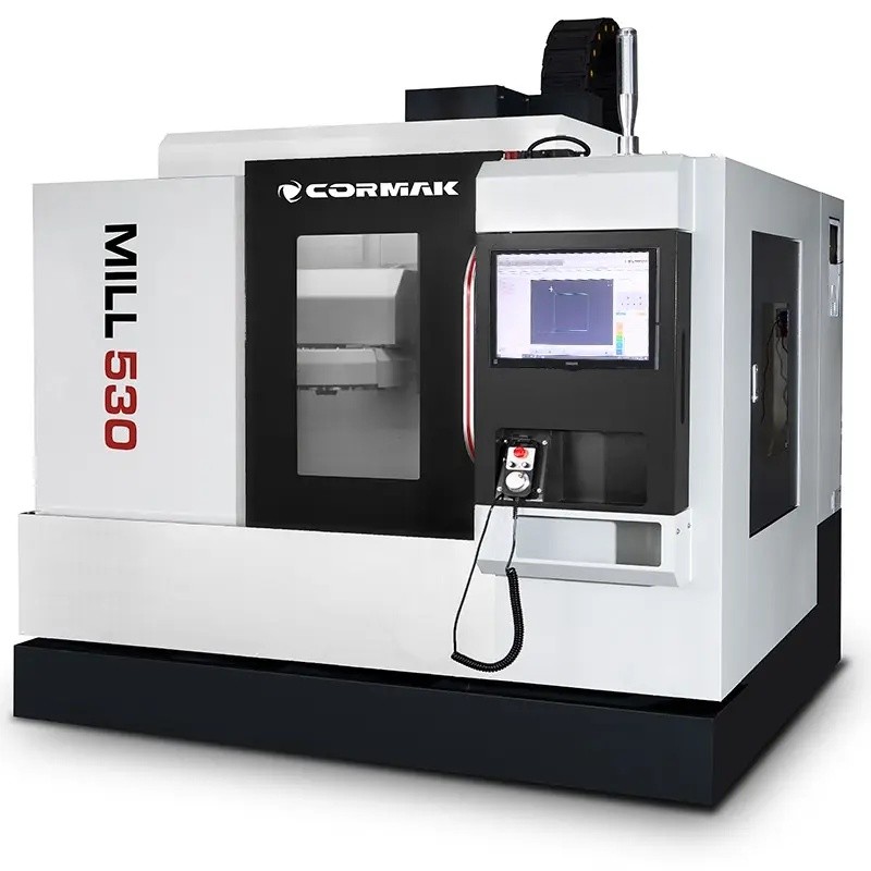
CNC machines of the machining centre class enable a wide range of machining operations to be carried out in a single workpiece set-up. Depending on the spindle orientation and the support structure, there are three main types: vertical, gantry and horizontal. Each has specific characteristics resulting from its kinematic configuration, which directly influences the type of workpieces that can be machined and the nature of the production process. The following article outlines the characteristics of each type and compares them side by side to help readers navigate the range of available solutions.
CNC machines of the machining centre class enable a wide range of machining operations to be carried out in a single workpiece set-up. Depending on the spindle orientation and the support structure, there are three main types: vertical, gantry and horizontal. Each has specific characteristics resulting from its kinematic configuration, which directly influences the type of workpieces that can be machined and the nature of production. The article below outlines the characteristics of each type and compares them side by side to help readers navigate the range of available solutions.
Contents
- Vertical CNC machining centres
- Gantry-type CNC machining centres
- Horizontal CNC machining centres
- Comparison table
- Summary
Vertical CNC machining centres
Design and operating principle
In vertical machining centres, the spindle is positioned vertically, perpendicular to the worktable. The cutting tool operates from above on the workpiece, which is clamped to the horizontal table. The X and Y axes provide feed movement in the horizontal plane, whilst the Z axis controls tool advance. The machine body is usually made of cast iron, which ensures vibration damping and rigidity during machining. Linear guides and ball screws ensure positioning accuracy to within a few micrometres. Spindles reach speeds ranging from a few to several thousand revolutions per minute, depending on the model.
The worktable is fitted with T-slots or a pallet system enabling the rapid clamping of tool holders and vices. An automatic tool changer (ATC) allows subsequent operations to be carried out without operator intervention. Many models available in the CORMAK range are fitted with Siemens Sinumerik or Fanuc control systems, ensuring support for advanced machining cycles and compatibility with CAD/CAM software.
Typical operations
-
Milling of surfaces, pockets, contours and curves
-
Drilling holes in various patterns
-
Machine threading
-
Reaming and countersinking holes
-
Machining of moulds and dies
-
5-axis machining on models with a tilting head or a rotary-tilting table
Typical applications and industries
Vertical machining centres are particularly widespread wherever precise machining of moderately sized components with complex geometries is required. They are standard equipment in the automotive industry, where engine components, gearboxes, suspension parts and casings are manufactured. In the aerospace industry, they are used to machine parts with stringent dimensional tolerance requirements. They are also used in the engineering industry, tool-making workshops, in the production of injection moulds and stamping dies, as well as in the furniture industry for machining metal components.
The materials machined primarily include carbon steel, alloy steel, cast iron, aluminium, brass, copper and plastics. A vertical machining centre is well suited to single-unit production, small-batch production and prototyping.
CNC gantry machining centres
Design and operating principle
Gantry-type machining centres are characterised by a distinctive gantry-shaped support structure: two vertical columns connected by a horizontal crossbeam form a gantry along which the spindle carriage moves. The large-surface worktable is either fixed or moves longitudinally. The spindle may be vertical or horizontal depending on the model, and its head is often tiltable, which allows machining at various angles. The solid, rigid gantry structure minimises deflection and vibration under high cutting forces, which is crucial when machining heavy workpieces.
Machines in this category offer a significantly larger working area than vertical machining centres. The permissible weight of the clamped workpiece is many times higher. The table, featuring T-slots or an integrated clamping system, accommodates workpieces of non-standard dimensions and weight.
Typical operations
-
Milling of large-scale surfaces and contours
-
Drilling and tapping holes in large components
-
Machining of pockets and grooves in heavy castings and forgings
-
Multi-surface machining using a tilting head
-
Turning on models with a rotary table turning function
Typical applications and industries
Gantry-type machining centres are primarily designed for the heavy industry sector. They are used in workshops specialising in the machining of large-scale castings and forgings, machine components, load-bearing frames, plain bearings, gearbox housings and gearboxes. They are used in the production of large-scale moulds for pressing and casting, both metal and plastic. The sectors in which they are most commonly used include: the power industry (turbines, generators), heavy machinery manufacturing, shipbuilding, the railway industry and the defence sector.
The materials machined are mainly structural and alloy steel, cast iron, aluminium in large cross-sections and special castings. The gantry-type machining centre is suited to the production of single-off and small-batch components whose weight and dimensions make machining on other types of machine impossible.
Horizontal CNC machining centres
Design and operating principle
In horizontal machining centres, the spindle axis is positioned horizontally. The workpiece is clamped to the table, which usually features a fourth rotary axis (B-axis), enabling indexing or continuous circumferential machining without the need to reposition the workpiece. Chips fall away from the cutting zone by gravity, which minimises their impact on surface quality and reduces the risk of tool damage caused by secondary cutting. The machine has a robust construction, and the use of linear guides and precision ball screws ensures high positioning repeatability. Siemens or Fanuc control systems enable the execution of complex multi-axis cycles.
The PREMIUM LINE series of horizontal machining centres available in CORMAK’s range of metalworking machines, such as the H-MILL 320, H-MILL 500, H-MILL 630 and H-MILL 800, are built using components from leading manufacturers (HIWIN, FANUC, Siemens, Bosch Rexroth, FAG), which ensures reliability in continuous production environments.
Typical operations
-
Multi-surface milling in a single set-up thanks to a rotary table
-
Drilling, threading and reaming of holes on different faces of the workpiece
-
Machining of long shafts, sleeves and cylindrical components
-
Series production of components with repeatable tolerances
-
Machining of heavy workpieces with efficient chip removal
Typical applications and industries
Horizontal machining centres are most commonly chosen where production is of a serial or mass nature and requires multi-sided machining with short cycle times. The rotary table allows access to four sides of the workpiece without repositioning it, which significantly reduces the number of set-ups and shortens production time. Gravity-fed chip removal makes them particularly suitable for deep machining of cast iron and steel, where large quantities of chips are generated.
Applications include the automotive industry (engine blocks, cylinder heads, gearboxes), the hydraulics industry (manifolds, valves, pump housings), the engineering industry (machine bodies, gearboxes) and the aerospace industry. The horizontal machining centre is a standard component of automated production lines featuring pallet systems and robotic loading.
Comparison table
|
Feature |
Vertical machining centre |
Gantry-type machining centre |
Horizontal machining centre |
|
Spindle orientation |
Vertical |
Vertical or multi-directional (tilting head) |
Horizontal |
|
Workpiece dimensions |
Small and medium |
Large and very large |
Small, medium and large |
|
Workpiece weight |
Up to several hundred kg |
Up to several tonnes and more |
Up to several hundred kg and more |
|
Chip removal |
Limited (chips accumulate in the cutting zone) |
Varies depending on the configuration |
Gravity-fed, free-flowing |
|
Multi-sided machining |
Limited (requires repositioning or a rotary table) |
Possible with a tilting head |
Natural thanks to the fourth rotary axis |
|
Production type |
Single-piece, small-batch, prototypes |
Single-unit, small-batch (oversized) |
Series production, mass production, automated production lines |
|
Typical industries |
Automotive, aerospace, toolmaking, furniture manufacturing |
Power generation, shipbuilding, railways, defence, heavy engineering |
Automotive, hydraulics, aerospace, engineering |
|
Typical materials |
Steel, aluminium, cast iron, brass, plastics |
Structural and alloy steel, cast iron, large castings |
Steel, cast iron, aluminium, special alloys |
|
Footprint |
Small to moderate |
Large |
Moderate to large |
Summary
Vertical, gantry and horizontal machining centres are three distinct classes of machine, each of which meets different production needs. Vertical machining centres are ideal for the precision machining of components of moderate size across a wide range of industries. Gantry-type machining centres are designed to meet the needs of heavy industry, where the dimensions and weight of workpieces exceed the capabilities of standard machines. Horizontal machining centres are designed for mass production, offering multi-sided machining in a single set-up and efficient chip removal.
The choice of a specific solution depends on the nature of production, the dimensions and weight of the workpieces, the required number of set-ups and the planned scale of production. The full range of all types can be viewed in the CNC machining centre category. If selecting the right model for a specific application requires technical consultation, CORMAK’s specialists are available via the contact details provided on the individual product pages and will be happy to help match the machine to your facility’s requirements.
